Sunday, August 31, 2014

Annex-1

Figure 1– Modified USNA Yard Patrol Craft Body Plan
Figure 2 – Modified Lines Plan of the USNA Yard Patrol Craft
Figure 3 – USNA YARD PATROL CRAFT - TABLE OF OFFSETS
Figure 4 - USNA Yard Patrol Craft Curves of Form

Wednesday, August 6, 2014

Curves of Form

All the geometric properties of a ship as a function of mean draft have been computed and put into a single graph for convenience. This graph is called the “curves of form”. Each ship has unique curves of form. There are also tables with the same information which are called the tabular curves of form.

It is difficult to fit all the different properties on a single sheet because they vary so greatly in magnitude. To fit all the curves on a single sheet of paper one of two things must be done.

One: Provide a series of different scales on the “x” axis so that each property has its own “x” axis scale.

Two: Plot each characteristic against a common scale on the “x” axis and use a scaling factor to bring the curves numerically closer.

Using the second method requires you to read a value off the common scale and then multiply that value by the curves scale factor to obtain the real value. Each scale factor also has units associated with it. Don’t forget to do this extra step!

There are curves of form for common navy ships in the back of this text under the “Ship’s Data” section. For convenience the curves of form for the Naval Academy’s Yard Patrol Craft has been provided at Figure 4 of Annex-1 as well as in the back in the “Ship’s Data” section.

The curves of form assume that the ship is floating on an even keel (i.e. zero list and zero trim). If the ship has a list or trim then the ship’s mean draft should be use when entering the curves of form.

Keep in mind that all properties on the “curves of form” are functions of mean draft and geometry. When weight is added, removed, or shifted, the operating waterplane and submerged volume change form so that all the geometric properties also change.

In typical calculations only small draft changes occur so that the properties in the curves of form also only undergo small changes. This means for most problems it doesn't matter if you look up the properties at the initial mean draft, final mean draft, or average mean draft. Numerically they all will be very close and shouldn't affect your final answer. If the draft changes by an amount that causes large changes in the properties, then an average draft of the initial and final drafts should be used.


Curve of Form Definitions


The following is a list of each characteristic found on the “curves of form” with a brief explanation of its meaning.


Displacement (Δ)

This is the weight of the water displaced by the ship for a given draft assuming the ship is in salt water with a density of 1.99 lb s2 / ft4. For a freely floating ship in salt water this is numerically equal to the weight of the ship. The typical unit on displacement for Naval Ships is the long ton. One long ton (LT) equals 2240 lb.


Other disciplines of science also use the word ton as follows. A long ton (LT) is the same as the ton equal to 2240 lb. A short ton (ST) is equal to 2000 lb . A metric ton (Tonne) is equal to 1000 kg. In this course “ton” will always mean 2240 lb.


LCB

This is the longitudinal center of buoyancy. It is the distance in feet from the longitudinal reference position to the center of buoyancy. The reference position could be the FP or midships. If it is midships remember that distances aft of midships are negative.


VCB

This is the vertical center of buoyancy. It is the distance in feet from the baseplane to the center of buoyancy. Sometimes this distance is labeled KB with a bar over the letters.


Immersion or TPI

TPI stands for tons per inch immersion or sometimes just called immersion. It is just what the words say it is. TPI is defined as the tons required to obtain one inch of parallel sinkage in salt water. Parallel sinkage is when the ship changes it’s forward and after drafts by the same amount so that no change in trim occurs.

To obtain just parallel sinkage the weight added would need to be “effectively” added to the center of flotation because the center of flotation is the pivot point of the ship while it is floating. The units on TPI are long tons per inch. If an equivalent weight is removed than you lose one inch of parallel sinkage. You will be using TPI in chapter 3 when you do trim problems.


An approximate formula for TPI based on the area of the waterplane can be derived as follows:


Note 1: Archimedes equation has been used to convert weight to the product of volume, density, and the magnitude of the acceleration of gravity.

Note 2: TPI is defined for a ship in salt water at 59 degrees Fahrenheit which allows the use of 1.99 lb s2 / ft4 for the density.

Note 3: It is assumed that the waterplane area doesn’t change much in one inch so that the volume required for one inch of submergence can be approximated by the product of the waterplane area and 1 inch of thickness. This is the same as assuming the volume is a right prism with the waterplane as the cross section and a height of one inch.


To calculate the change in draft due to parallel sinkage the following equation is used:


WPA or Awp


WPA or Awp stands for the waterplane area. The units of WPA are ft2. This waterplane area can be calculated with Simpson’s rule.


LCF


LCF is the longitudinal center of flotation. It is the distance in feet from the longitudinal reference to the center of flotation. The reference position could be the FP or midships. If it is midships remember that distances aft of midships are negative. The LCF can be calculated using table of offsets and Simpson’s rule.


Moment/ Trim 1" or MT1"

This stands for the moment to change trim one inch. The units are LT-ft per inch. The ship will rotate about the center of flotation when a moment is applied to it. The moment can be produced by adding, removing, or shifting a weight some distance from the center of flotation. There are an infinite number of possible combinations of weights and distances to achieve the moment. 

Trim is defined as the draft aft minus the draft forward. 
By convention when a ship is down by the bow it is assigned a negative trim.


To compute the change in trim due to a weight shift or addition the following equation is used:

KML


This stands for the distance in feet from the keel to the longitudinal metacenter. For now just assume the metacenter is a convenient reference point vertically above the keel of the ship for Naval Architecture calculations. This distance is on the order of one hundred to one thousand feet whereas the distance from the keel to the transverse metacenter is only on the order of ten to thirty feet.


KMT

This stands for the distance in feet from the keel to the transverse metacenter. Typically, Naval Architects do not bother putting the subscript “T” for any property in the transverse direction because it is assumed that when no subscript is present the transverse direction is implied.

You have done the calculations for at least two of the properties listed in the curves of form. This should have given you an appreciation for how the curves of form are constructed. Given more time and a little more instruction you could use a table of offsets and numerical integration to obtain the rest of the properties. Be grateful that all these calculations have been done already so that all you have to do is look up these values.

Be sure that, given a ship’s curves of form and a mean draft, you can find any of the properties listed above. You will need this skill to obtain the values for calculations that will follow in subsequent chapters.

Tuesday, August 5, 2014

Hull Form Characteristics

The hull form characteristics applicable to the profile view of a ship have already been discussed. However, there are a number of others which are relevant to a view of the ship from the bow or stern.

As mentioned previously, the keel is at the bottom of the ship. The bottoms of most ships are not flat. Distances above the keel are usually measured from a constant reference plane, the base-plane. The keel is denoted by "K" on diagrams with the distance above the keel being synonymous with the distance above the baseline.

Depth (D), Draft (T) and Beam (B)

The depth of the hull is the distance from the keel to the deck. Sometimes the deck is cambered, or curved, so the depth may also be defined as the distance from the keel to the deck at the intersection of deck and side or the “deck at edge”. The symbol used for depth is "D". The depth of the hull is significant when studying the stress distribution throughout the hull structure.

The draft (T) of the ship is the distance from the keel to the surface of the water. The mean draft is the average of the bow and stern drafts at the perpendiculars. The mean draft is the draft at amidships.
Freeboard is the difference between “D” and “T”.

The beam (B) is the transverse distance across each section. Typically when referring to the beam of a ship, the maximum beam at the DWL is implied.

Figure below shows the dimensions of these terms on a typical midship section of a ship.
Figure: Hull Form Characteristics

Flare and Tumblehome

The forward sections of most ships have a bow characteristic called flare. On a flared bow, the half-breadths increase as distance above the keel increases. Flare improves a ship's performance in waves, and increases the available deck space.

Tumblehome is the opposite of flare. It is uncommon on modern surface ships. However, sailing yachts and submarines do have tumblehome. Figure below shows flare and tumblehome.
Figure: Ships with Flare and Tumblehome

Centroids

A centroid is defined as the geometric center of a body.

The center of mass is often called the center of gravity and is defined as the location where all the body’s mass or weight can be considered located if it were to be represented as a point mass.
If the object has uniform density and thickness, then the centroid will be coincident with the body’s center of mass.

Conceptually, and in their application to ships, there is a big difference between a centroid and a center of mass.

Both centroids and centers of mass can be found by doing weighted averages as discussed in chapter one. For example, Figure below is a two dimensional uniform body with an irregular shape. The “Y” location of the centroid of this shape can be found by breaking the area up into little pieces and finding the average “Y” distance to all the area. This can be repeated for the “X” location of the centroid. This will result in the coordinates of the centroid of the area shown with respect to the arbitrary coordinate system chosen.
Figure: Showing the Calculation of a Centroid of an Irregular Plane Area

Two Very Important Centroids - The Center of Flotation and The Center of Buoyancy

The concept of a centroid is important in Naval Engineering because it defines the location of two extremely useful points in the analysis of the statical stability of a ship.

Center of Flotation (F)

The centroid of the operating waterplane is the point about which the ship will list and trim. This point is called the center of flotation (F) and it acts as a fulcrum or pivot point for a floating ship.

The distance of the center of flotation from the centerline of the ship is called the “transverse center of flotation” (TCF). When the ship is upright the center of flotation is located on the centerline so that the TCF = 0 feet.

The distance of the center of flotation from amidships (or the forward or after perpendicular) is called the “longitudinal center of flotation” (LCF). When writing a LCF distance you must state if it’s from midships or from one of the perpendiculars so the person reading the value will know where it’s referenced from. If the reference is amidships you must also indicate if the distance is forward or aft of midships. By convention, a negative sign is used to indicate distances aft of midships.

The center of flotation is always located at the centroid of the current waterplane. When the ship lists to port or starboard, or trims down by the bow or stern, or changes draft, the shape of the waterplane will change, thus the location of the centroid will move, leading to a change in the center of flotation.

Center of Buoyancy (B)

The centroid of the underwater volume of the ship is the location where the resultant buoyant force acts. This point is called the center of buoyancy (B) and is extremely important in static stability calculations.

The distance of the center of buoyancy from the centerline of the ship is called the “transverse center of buoyancy” (TCB). When the ship is upright the center of buoyancy is located on the centerline so that the TCB = 0 feet.

The vertical location of the center of buoyancy from the keel (or baseplane) is written as “VCB” or as "KB" with a line over the letters “KB” indicating it is a line segment from point “K” to point “B”.

The distance of the center of buoyancy from amidships (or the forward or after perpendicular) is called the “longitudinal center of buoyancy” (LCB). When writing a LCB distance you must state if it’s from midships or from one of the perpendiculars so the person reading the value will know where it’s referenced from. If the reference is amidships you must also indicate if the distance is forward or aft of midships. Recall that a negative sign is used to indicate distances aft of midships.

The center of buoyancy is always located at the centroid of the submerged volume of the ship. When the ships lists to port or starboard, or trims down by the bow or stern, or changes draft, the shape of the submerged volume will change, thus the location of the centroid will move and alter the center of buoyancy.

Monday, August 4, 2014

Representation of Hull Form

A ship's hull is a very complicated 3 dimensional shape. With few exceptions an equation cannot be written that fully describes the shape of a ship. Therefore, engineers have placed great emphasis on the graphical description of hull forms. Until very recently, most of this work was done by hand. Today high-speed digital computers assist the engineer with the drawings, but they are not substitutes for imagination and judgment.

Traditionally, the ship's hull form is represented graphically by a lines drawing. The lines drawing consist of projections of the intersection of the hull with a series of planes. The planes are equally spaced in each of the three dimensions. Planes in one dimension will be perpendicular to planes in the other two dimensions. We say that the sets of planes are mutually perpendicular or orthogonal planes.

The points of intersection of these planes with the hull results in a series of lines that are projected onto a single plane located on the front, top, or side of the ship. This results in three separate projections, or views, called the Body Plan, the Half-Breadth Plan, and the Sheer plan, respectively. Figure 2 displays the creation of these views.


Representing a 3 dimensional shape with three orthogonal plane views is a common practice in engineering. The engineer must be able to communicate an idea graphically so that it can be fabricated by a machinist or technician. In engineering terms this type of mechanical drawing is referred to as an “orthographic plate” because it contains three orthogonal graphic pictures of the object. Orthographic projections are used in all engineering fields.

To visualize how a “lines drawing” works, place the ship in an imaginary rectangular box whose sides just touch the keel and sides of the ship. The bottom, side and front of the box will serve as the basis for three orthogonal projection screens on which lines will be projected onto. The lines to be projected result from the intersection of the hull with planes that are parallel to each of the three orthogonal planes mentioned. Refer to Figure below.

Figure: The Projection of Lines onto 3 Orthogonal Planes


The Half-Breadth Plan

The bottom of the box is a reference plane called the base plane. The base plane is usually level with the keel. A series of planes parallel and above the base plane are imagined at regular intervals, usually at every foot. Each plane will intersect the ship's hull and form a line at the points of intersection. These lines are called “waterlines” and are all projected onto a single plane called the “Half Breadth Plan”. Figure below shows the creation of this plan.


Each waterline shows the true shape of the hull from the top view for some elevation above the base plane which allows this line to serve as a pattern for the construction of the ship’s framing. The grid network on the half-breadth plan is straight lines that represent the orthogonal planes containing the buttock and station lines.


Figure: The Half-Breadth Plan

The waterlines referred to here have nothing to do with where the ship actually floats. These waterlines are the intersection of the ship’s hull with some imaginary plane above the base plane. There will be one plane above the base plane that coincides with the normal draft of the ship, this waterline is called the “Design Water Line”. The design water line is often represented on drawings as “DWL” or “∇”.

Since ships are symmetric about their centerline they only need be drawn for the starboard or port side, thus the name of “Half Breadth Plan”.


The Sheer Plan

A plane that runs from bow to stern directly through the center of the ship and parallel to the sides of the imaginary box is called the centerline plane. A series of planes parallel to one side of the centerline plane are imagined at regular intervals from the centerline. Each plane will intersect the ship's hull and form a curved line at the points of intersection. These lines are called “buttock” or “butt lines” and are all projected onto a single plane called the “Sheer Plan”. Figure below shows the creation of this plan.


Each buttock line shows the true shape of the hull from the side view for some distance from the centerline of the ship. This allows them to serve as a pattern for the construction of the ship’s longitudinal framing. The grid network on the sheer plan is straight lines that represent the orthogonal planes containing the station lines and waterlines.

The centerline plane shows a special butt line called the “profile” of the ship.

The sheer plan gets its name from the idea of a sheer line on a ship. The sheer line on a ship is the upward longitudinal curve of a ship’s deck or bulwarks. It is the sheer line of the vessel which gives it a pleasing aesthetic quality.


Figure: The Sheer Plan


The Body Plan

Planes parallel to the front and back of the imaginary box running port to starboard are called stations. A ship is typically divided into 11, 21, 31, or 41 evenly spaced stations. The larger the ship the more stations will be made. An odd number of stations results in an even number of equal blocks between the stations.

The first forward station at the bow is usually labeled station number zero. This forward station is called the forward perpendicular (FP). By definition the FP is located at a longitudinal position as to intersect the stem of the ship at the DWL.

The after-most station is called the after perpendicular (AP). By definition the AP is located at a longitudinal position as to intersect the stern at the DWL for ships with a transom stern or alternatively through the rudder stock of the vessel.

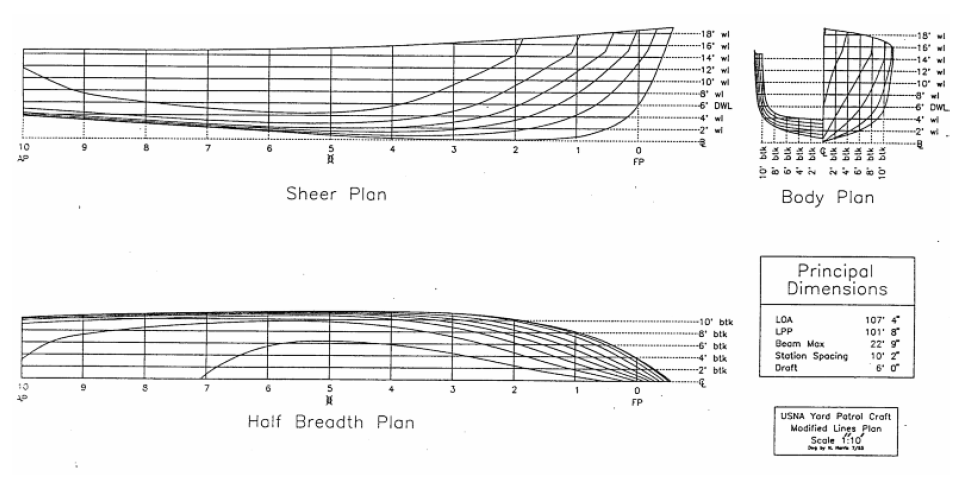
The station midway between the perpendiculars is called the midships station, usually represented by the symbol. The length between perpendiculars has the symbol “Lpp”. Engineers typically use the Lpp for calculations. There is also an overall ship length “LOA” that might be a more useful number to use if you were docking the ship. Figure below displays these hull form characteristics.

Figure: Hull Form Nomenclature

Each station plane will intersect the ship's hull and form a curved line at the points of intersection. These lines are called “sectional lines” and are all projected onto a single plane called the “Body Plan”. Refer to Figures below.

The body plan takes advantage of the ship's symmetry. Only half of each section is drawn because the other half is identical. By convention, the sections forward of amidships are drawn on the right side, and the sections aft of amidships are drawn on the left side. The amidships section is generally shown on both sides of the body plan. The vertical line in the center separating the left and right half of the ship is called the centerline.

Each sectional line shows the true shape of the hull from the front view for some longitudinal position on the ship which allows this line to serve as a pattern for the construction of the ship’s transverse framing. The grid network on the body plan is straight lines that represent the orthogonal planes containing the buttock lines and waterlines.


Figure: The Body Plan


Table of Offsets

To calculate geometric characteristics of the hull using numerical techniques, the information on the lines drawing is converted to a numerical representation in a table called the table of offsets.

The table of offsets lists the distance from the center plane to the outline of the hull at each station and waterline. This distance is called the “offset” or “half-breadth distance”. By convention this is the “y” direction.

Enough information is usually given in the table of offsets to produce all three plans of the lines plan. The table of offsets is used to calculate geometric properties of the hull such as sectional area, waterplane area, submerged volume and the longitudinal center of flotation.

Sunday, August 3, 2014

Categories of Seagoing Vessels


1. Aerostatic Support
Aerostatic support is achieved when the vessel rides on a cushion of air generated by lift fans. These vessels tend to be lighter weight and higher speed vessels. The two basic types of vessels supported aerostatically are air cushion vehicle (ACV) and surface effect ships (SES). See Figure 1.

1.1 Air Cushion Vehicles (ACVs)
Air Cushion Vehicles (ACVs) or hovercraft continuously force air under the vessel allowing some of the air to escape around the perimeter as new air is forced downwards. They are usually propelled forward by airplane propeller type devices above the surface of the water with rudders behind the air flow to control the vessel.

Hovercrafts are very expensive for their size, but have the unique property of being amphibious. The Navy utilizes some hovercraft as LCACs (Landing Craft Air Cushion vehicles) because of this ability. Their use has opened over 75% of the world's coastline to amphibious assault compared with 5% with conventional landing craft.

1.2 Surface Effect Ship (SES)
The Surface Effect Ship (SES) or Captured Air Bubble (CAB) craft, are similar to ACV’s in that they use a cushion of air to lift the vessel. However, the SES has rigid side walls that extend into the water. This prevents the SES from being amphibious but reduces the air pumping requirements and makes them more directionally stable. The side walls also contribute to the hydrostatic or hydrodynamic support of the craft allowing the SES to carry more payload. They are usually propelled by water jets or super cavitating propellers.

2. Hydrodynamic Support

Hydro is the prefix for water and dynamic indicates movement. The two basic types of vessels supported hydrodynamically are planing vessels and hydrofoils.

2.1 Planing Vessels
Planing vessels use the hydrodynamic pressures developed on the hull at high speeds to support the ship. They are very fast, some capable over 50 knots. In smooth water they ride very comfortably. When moving through waves, planing vessels ride very roughly, heavily stressing both the vessel structure and passengers. This was particularly true of older types which used relatively flat bottom hulls. Modifications to the basic hull form, such as deep V-shaped sections, have helped to alleviate this problem somewhat. Planing hulls require much larger engines for their size than displacement hulls.

These factors above serve to limit the size of planing vessels. However, these ships are used in a variety of roles such as pleasure boats, patrol boats, missile boats, and racing boats.

At slow speeds the planing craft acts like a displacement ship and is supported hydrostatically.


2.2 Hydrofoils
Hydrofoil craft are supported by underwater foils, not unlike the wings of an aircraft. At high speeds these underwater surfaces develop lift and raise the hull out of the water. Bernoulli’s Principle is often used to explain how a wing develops lift. These vessels are very fast, reaching speeds of 40 - 60 knots and compared to planing boats, hydrofoils experience much lower vertical accelerations in moderate sea states making them more comfortable to ride.

The hydrofoil can become uncomfortable or even dangerous in heavy sea states due to the foils breaking clear of the water and the hull impacting the waves. If the seaway becomes too rough the dynamic support is not used, and the ship becomes a displacement vessel.

The need for the hydrofoils to produce enough upward force to lift the ship out of the water places practical constraints on the vessel's size. Therefore, the potential crew and cargo carrying capacity of these boats is limited. Hydrofoils are also very expensive for their size in comparison to conventional displacement vessels.

3. Hydrostatic Support
Hydrostatically supported vessels are by far the most common type of water borne craft. They describe any vessel that is supported by “Archimedes Principle”.

Word definition of Archimedes Principle

“An object partially or fully submerged in a fluid will experience a resultant vertical force equal in magnitude to the weight of the volume of fluid displaced by the object.”

In EN200, this force is called the “buoyant force” or the “force of buoyancy”.

Archimedes Principle can be written in mathematical format as follows.


3.1 Displacement Ships
Hydrostatically supported ships are referred to as “displacement ships”, since they float by displacing their own weight in water, according to Archimedes Principle. These are the oldest form of ships coming in all sizes and being used for such varied purposes as hauling cargo, bulk oil carrying, launching and recovering aircraft, transporting people, fishing, and war fighting.


Displacement hulls have the advantage of being a very old and common type of ship. Therefore, many aspects of their performance and cost have been well studied. In comparison to other types of vessels the cost of displacement ships is fairly low with respect to the amount of payload they can carry.

Disadvantages of displacement vessels include their limited speed and at times, their seakeeping ability (how they respond to ocean waves).

3.2 SWATH
A special displacement ship is the Small Waterplane Area Twin Hull (SWATH). Most of the underwater volume in the SWATH ship is concentrated well below the water's surface as shown in Figure 2-1. This gives them very good seakeeping characteristics. They also have a large open deck and are therefore useful in a variety of applications requiring stable platforms and a large expanse of deck space. SWATH vessels are currently utilized as cruise ships, ferries, research vessels, and towed array platforms.

Two major disadvantages of SWATH ships are deep draft and cost. Additionally, these vessels present the designer with structural problems differing from other ships, particularly with respect to transverse bending moments.

3.3 Submarines
Submarines are hydrostatically supported but above 3 to 5 knots depth control can be achieved hydrodynamically due to the lift created by the submarines planes and body of the hull.

Submarines have typically been used as weapons of war, but lately have also seen some non-military application. Some submarines are being designed for the purpose of viewing underwater life and reefs, for example. Unmanned submersibles have been used for scientific purposes, such as finding the Titanic, as well as a wide variety of oceanographic research.

There are many differences between the engineering problems faced by the surface ship designer and those faced by the submarine designer. Many of these differences will be covered in the last chapter of this course.

Saturday, August 2, 2014

Introduction to Ships and Naval Engineering

Introduction

Ships are the single most expensive product a nation produces for defense, commerce, research, or nearly any other function. If we are to use such expensive instruments wisely we must understand how and why they operate the way they do.

Ships employ almost every type of engineering system imaginable. Structural networks hold the ship together and protect its contents and crew. Machinery propels the ship and provides for all of the needs of the ship's inhabitants. Every need of every member of the crew must be provided for: cooking, eating, trash disposal, sleeping, and bathing. The study of ships is a study of systems engineering.

There are many types of ships from which to choose from and each type has its advantages and disadvantages. Factors which may influence the ship designer's decisions or the 
customer's choices include: cost, size, speed, seakeeping, radar signature, draft, maneuverability, stability, and any number of special capabilities. The designer must weigh all of these factors, and others, when trying to meet the customer's specifications. Most ships sacrifice some characteristics, like low cost, for other factors, like speed.

The study of Naval Engineering is the merging of the art and craft of ship building with the principles of physics and engineering sciences to meet the needs of a naval vessel in the security and defense of our nation.. It is the study of the research, development, design, construction, operation, maintenance, and logistical support of our naval vessels. This introductory course in Naval Engineering is meant to give each student an appreciation in each of the more common areas of study. It is meant as a survey course that will give some good practical knowledge to every officer assigned to naval service on land, sea or in the air.


Categorizing Ships

The term “ship” can be used to represent a wide range of vessels operating on, above or below the surface of the water. To help organize this study ships are often categorized into groups based on either usage or means of support while in operation or both.

A list of classification by usage might include the following.

  • Merchant Ships: These ships are intended to earn a profit in the distribution of goods. A cash flow analysis is done of income versus costs in the calculation of a rate of return on the investment. Engineering economy studies must include receipts earned, acquisition costs, operating and maintenance costs, and any salvage value remaining when the ship is sold in a time value of money study.
  • Naval and Coast Guard Vessels: Classified as combatants or auxiliaries. These ships tend to be extremely expensive because their missions require many performance capabilities such as speed, endurance, weapons payload, ability to operate and survive in hostile environments and reliability under combat conditions.
  • Recreational and Pleasure Ships: Personal pleasure craft and cruise liners are a specialized class of ships that are run to earn a profit by providing recreation services to the general public. Comfort and safety are of utmost importance.
  • Utility Tugs: Designed for long operation and easy maintenance with a no frills approach.
  • Research and Environmental Ships: Highly specialized equipment must be kept and often deployed into and out of the water.
  • Ferries: People and Vehicles must be able to be loaded and unloaded with efficiency and safety in accordance with a strict time schedule in all weather conditions.

Ships can also be classified by the means of physical support while in operation. Three broad 
classifications that are frequently used by naval architects as shown at Figure 1 reproduced from an “Introduction to Naval Architecture” by Gillmer and Johnson.

  • Aerostatic Support
  • Hydrodynamic Support
  • Hydrostatic Support
Figure 1 - Categories of Seagoing Vessels According to Their Mode of Support


Friday, August 1, 2014

Engineering Fundamentals

Pressure and Hydrostatic Pressure

On the most fundamental level, pressure is the effect of molecules colliding. All fluids (liquids and gases), have molecules moving about each other in a random chaotic manner. These molecules will collide and change direction exerting an impulse. The sum of all the impulses produces a distributed force over an area which we call pressure. Pressure has units of pounds per square inch (psi).

There are actually three kinds of pressure used in fluid dynamics. They are static, dynamic, and total pressure. The pressure described in the first paragraph is static pressure. Dynamic pressure is the pressure measured in the face of a moving fluid. Total pressure is the sum of static and dynamic pressure. If a fluid is assumed to be at rest, dynamic pressure is equal to zero. The pressures we will be using in this course will be based on fluids being at rest.

Consider a small object sitting in water at some depth, z. If the object and water are at rest (velocity equals zero), then the sum of all forces acting on the object is zero, and the dynamic pressure acting on the object is zero. The pressure that the water exerts on the object is static pressure only; in the analysis of fluids, this static pressure is referred to as “hydrostatic pressure.” Hydrostatic pressure is made up by distributed forces that act normal to the surface of the object in the water. These forces are referred to as “hydrostatic forces”. The hydrostatic forces can be resolved into horizontal and vertical components. Since the object is in static equilibrium, the horizontal components of hydrostatic force must sum to zero and cancel each other out. For the object to remain at rest, the vertical component of hydrostatic force must equal the weight of the column of water directly above the object. The weight of the column of water is determined using the equation:

Weight = (density) × (gravity) × (volume of water)
W = ρgV = ρgAz

Where:
ρ = water density (lb-s2/ft4)
g = acceleration of gravity (ft/s2)
A = surface area of the object (ft2)
z = depth of the object below the water’s surface (ft)

Therefore, the hydrostatic force acting on an object at depth, z is equal to:
Fhyd = ρgAz

Dividing hydrostatic force by the area over which it acts yields the hydrostatic pressure acting on the object:

Phyd = ρgz                   Þ        Fhyd = Phyd × Area


This equation can be used to find the hydrostatic pressure acting on any object at any depth. Note that hydrostatic pressure varies linearly with the depth of the object.


Bernoulli’s Equation

It is useful to have a short discussion of external fluid flow. This is the situation that occurs when water flows around a ship’s rudder, submarine planes, hydrofoils, or the hull of any vessel moving through the water. The study and analysis of fluid flow is a complex subject, a subject that will baffle researchers for many years to come. However, as students of naval engineering, you should have some basic knowledge of external fluid flow.

Consider a fluid flowing at some velocity, V. Now, think of a line of fluid molecules that are moving in a direction tangent to the fluid’s velocity. This line of movement is referred to as a streamline. One method of flow analysis is to consider the fluid to be made up of many streamlines, each layered on top of the other. We will be looking at a group of fluid molecules traveling along one streamline. To further our analysis of the fluid, the fluid flow is assumed to be incompressible, meaning that its density is not changing anywhere along the flow, and that there is no contraction or dilation of the fluid molecules. If the water molecules are not rotating, the flow is called irrotational and the fluid is said to have a vorticity of zero. If there are no shearing stresses between layers of the flow, the fluid is said to be inviscid. Finally, if we assume that a fluid’s properties at one point on the streamline do not change with time (although the fluid’s properties can change from location to location along the streamline), the fluid flow is said to be steady. In this course, our analysis will assume steady incompressible inviscid flow. 

For steady incompressible inviscid flow, the sum of the flow work plus the kinetic energy plus the potential energy is constant along a streamline. This is Bernoulli’s Equation and it can be applied to two different points along a streamline to yield the following equation:


The “p/ρ” term in the equation is the flow work at any point on the streamline, the “V2/2” term is the fluid’s kinetic energy at any point on the streamline, and the “gz” term is the fluid’s potential energy at any point on the streamline.


Using Bernoulli’s equation, we can explain why lift and thrust is generated by flow over hydrofoils, rudders, submarine planes, and propeller blades. We can also describe the pressure distribution of fluid flowing around a ship’s hull.

Definition of a Ship’s Axes and Degrees of Freedom


A ship floating freely in water is subject to six degrees of freedom (exactly the same as an airplane flying in the sky). There are three translational and three rotational degrees of freedom associated with a ship. As a quick review, translation refers to motion in a straight line and rotation refers to rotating or spinning about an axis.

In naval architecture, the longitudinal axis of a ship (meaning from bow to stern or stern to bow) is always defined as the x-axis. Motion in the longitudinal direction is referred to as surge. The x-axis of a ship is usually defined as the ship’s centerline with its origin at amidships and the keel. Therefore, positive longitudinal measurements are forward of amidships and negative longitudinal measurements are aft of amidships. Rotation about the x-axis is referred to as roll. Figure below shows the 6 degrees of freedom of a ship. There are also two static conditions of rotation about the x-axis. These are list and heel. List is a condition produced by a weight shift on the ship. Heel is a condition produced by an external force such as the wind.

A ship’s y-axis is used for measurements in the transverse or athwartships (port and starboard) direction. The y-axis has its origin at the keel and on the centerline. Naval architecture convention states that the positive y-direction is starboard of the centerline and that negative measurements are port of centerline. Translational motion in the y-direction is referred to as sway, and rotational motion about the y-axis is pitch. The static condition of rotation about the y-axis is referred to as trim. Similar to list, trim is a condition produced by a weight shift on the ship.

Vertical measurements in a ship are referenced to the keel. Therefore a ship’s vertical or z-axis has its origin at the keel and centerline. For most ships, the keel is also the baseline for vertical measurements. Translational motion in the z-direction is referred to as heave, and rotational motion about the z-axis is yaw.

As seen in the above paragraphs, the customary origin for a ship’s coordinate system is on the centerline, at the keel and amidships. Sometimes, for ease of computation, the longitudinal origin may be placed at the bow or stern.


Figure: A ship’s axes and degrees of freedom


Saturday, July 12, 2014

Engineering Drawing - Part 6

3D CAD & Solid Modelling


CAD technology.

Computer Aided Drafting or Design offers several methods of representing the design model:

2D - Lines and text, similar to conventional drawing board.
3D - Vertices (corners or points in space), edges, surfaces in x, y and z.
Solid modelling - Solid geometry, fully defined three dimensional solid shapes, with free-form curved faces, material and mass properties.

Different methods suit different design circumstances. This section will introduce you to the most significant and expanding technology, Solid Modelling.

The graph below gives a very crude indication of the productivity of companies developing CAD software, through time.

All of the acronyms below may be used in the context of mechanical computer aided engineering:

CAD - Computer Aided Design/Drafting
MCAD - Mechanical Computer Aided Design
CAE - Computer Aided Engineering

Part modelling

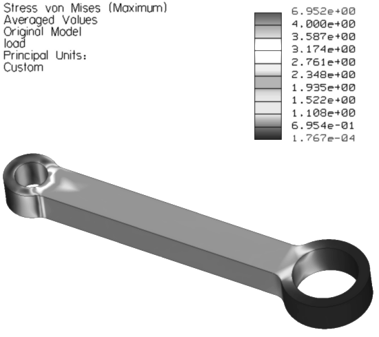
You can create 3D solid part models of your designs, such as this connecting rod. The dimensions that define the model are related to each other and can be changed and controlled. So, if you change one dimension, others will change with it. Software that allows this is refereed to as parametric. For example, change the centre distance of the bores of this connecting rod and the whole model will stretch out.

You can also assign material properties, analyse mass properties, control the colour and texture of the appearance, create photo realistic images with lighting, shadows and perspective.


Orthographic drawing


From the 3D model you can also create a detailed orthographic projection drawing. You can easily modify the design. Because the solid part file and the drawing file are connected, or associated with each other, a change in one will appear in the other. Change a dimension in the solid part and the same dimension will be updated in the drawing.

Most market leading solid modelling software offers this associativity and is usually referred to as 3D parametric associative solid modelling software.

Assembly modelling


Solid model parts can be assembled. The assembly files can enjoy the same associativity as do part and drawing files. The connecting rod above has been assembled here with a crank shaft and a piston.


Analysing your design


Having created a 3D solid model of a component, the geometry can then be used to predict how it may behave in real life.

For example:
To predict how high the stresses may be and how much the connecting rod may deflect under load, CAD software can be used to apply loads and supports and then analyse the structural behaviour of the model.

As the design engineer, you can use the analysis results to help you decide whether the design is acceptable or requires modification. You may decide for the connecting rod , that the stresses are too high around the small end and modify the design accordingly. You run the analysis again, continuing the process until the predicted stress values are acceptable.

Visualise your design


As time passes more and more 3D CAD software packages allow you to create high quality photorealistic images of your designs. By setting up an environment, with surrounding walls, a floor and a ceiling, lights, surface textures, etc. you can capture impressive images that cast shadows and reflections, giving a much more realistic impression of what your design may look like once manufactured. These facilities provide very powerful tools for developing, communicating and selling design ideas.

Most consumer product designs are modelled using 3D CAD software and then photo rendered as part of the product development process. Most public building designs now are also treated in the same way.


Friday, July 11, 2014

Engineering Drawing - Part 5

Tolerances, limits and fits

In order to ensure that assemblies function properly their component parts must fit together in a predictable way. As mentioned in section 2.5, no component can be manufactured to an exact size, so the designer has to decide on appropriate upper and lower limits for each dimension.

Accurately toleranced dimensioned features usually take much more time to manufacture correctly and therefore can increase production costs significantly. Good engineering practice finds the optimum balance between required accuracy for the function of the component and minimum cost of manufacture.


Dimension tolerances


If a dimension is specified, in millimeters, as 10 ± 0.02, the part will be acceptable if the dimension is manufactured to an actual size between 9.98 and 10.02 mm. Below are some examples of ways of defining such limits for a linear dimension.

To give you a feel for the magnitude of decimal values in mm, consider these facts:

The thickness of the paper this page is printed on is approximately 0.100 mm.

Average human hair thickness is approximately 0.070 mm.

The human eye cannot resolve a gap between two points smaller than about 0.020mm, at a 20cm distance.

If you raise the temperature of a 100mm long block of steel by 10ºC it will increase in length by approximately 0.020mm.


General tolerancing


General tolerance notes apply tolerances to all unspecified dimensions on a drawing. They can save time and help to make a drawing less cluttered. Examples are shown below.

Some examples of general tolerance notes

Limits and fits for shafts and holes


Basic size and shaft/hole tolerancing systems


The basic size or nominal size is the size of shaft or hole that the designer specifies before applying the limits to it. There are two systems used for specifying shaft/hole
tolerances:

Basic hole system: Starts with the basic hole size and adjusts shaft size to fit.


Basic shaft system: Starts with the basic shaft size and adjusts hole size to fit.


Because holes are usually made with standard tools such as drills and reamers, etc, the basic hole system tends to be preferred and will therefore be used here.


Fit


The fit represents the tightness or looseness resulting from the application of tolerances to mating parts, e.g. shafts and holes. Fits are generally classified as one of the
following:

Clearance fit: 
  • Assemble/disassemble by hand.
  • Creates running & sliding assemblies, ranging from loose low cost, to free-running high temperature change applications and accurate minimal play locations.

Transition fit: 
  • Assembly usually requires press tooling or mechanical assistance of some kind.
  • Creates close accuracy with little or no interference.

Interference fit: 
  • Parts need to be forced or shrunk fitted together.
  • Creates permanent assemblies that retain and locate themselves.


ISO limits and fits


Fits have been standradised and can be taken directly from those tabulated in the BS 4500 standard, 'ISO limits and fits.'

The BS 4500 standard refers to tolerance symbols made up with a letter followed by a number. The BS Data Sheet BS 4500A, as shown on the following two pages, shows a range of fits derived, using the hole basis, from the following tolerances:
Holes:
H11
H9
H8
H7

Shafts:
c11
d10
e9
f7
g6
k6
n6
p6
s6
Remember:
  • Capital letters always refer to holes, lower case always refer to shafts.
  • The greater the number the greater or wider the tolerances.
The selection of a pair of these tolerances will give you the fit. The number of possible combinations is huge. BS 4500 helps to standardize this and offers a range of fits suitable for most engineering applications.

Selected ISO Fits - Hole Basis. Extract from BS 4500, data Sheet 4500A.

Selected ISO Fits - Hole Basis. Extract from BS 4500, data Sheet 4500A.

ISO limits and fits, determining working limits


Consider an example of a shaft and a housing used in a linkage:

Type of fit:                                     
'Normal' clearance fit.
Basic or Nominal size:                  
φ40mm

We will determine the actual working limits, the range of allowable sizes, for the shaft and the hole in the housing.

Look along the bottom of the ISO Fits Data Sheet 4500A and locate 'Normal Fit'. We will use this pair of columns to extract our tolerances.

The tolerances indicated are:

1st column
H8
for the hole   (upper case H)
2nd column
f7
for the shaft  (lower case f)

The actual tolerances depend upon the basic, or nominal, diameter as well as the class of fit. So, locate 40mm in the left hand Nominal Sizes column. Either the 30 - 40 or 40 - 50 range is acceptable in this case. Read across and note the tolerance values for the hole and the shaft, as shown below.


For the hole diameter we have a tolerance of: +0.039mm   -0.000mm
For the shaft diameter we have a tolerance of: -0.025mm   -0.050mm

These tolerance values are simply added to the nominal size to obtain the actual allowable sizes.

Note that this is a clearance fit. As long as the hole and shaft are manufactured within the specified tolerances the hole will always be either slightly oversize or spot on the nominal size and the shaft will always be slightly under-size. This ensures that there will always be a free clearance fit.

These tolerances may be expressed on a drawing in several ways:


1) Simply as the nominal size with the tolerance class.

This is not always preferred as the machine operator has to calculate the working limits.


2) The nominal size with the tolerance class as above with the calculated working limits included.


3) The calculated working limits only.


Tabulated guide to types of ISO limits and fits


Assembly drawings


Assembly drawings can be used to:
  • Name, identify, describe and quantify all of the components making up the assembly.
  • Clearly show how all of the components fit together.
  • Indicate all of the required fasteners.
  • Record any special assembly instructions.
  • Record any other relevant information.
Here is an example:


Note the use of sections, item numbers neatly laid out and the parts list.

Drawing checklist

It is easy to accidentally omit various items when creating engineering detail drawings. Before passing on your work it is recommended that you work through the checklist below for each drawing:

The general drawing:

  1. Do projections conform to the relevant conventions, usually 1st or 3rd angle?
  2. Have you used the minimum number of views necessary to accurately show the information required?
  3. Are the views laid out in appropriate positions relative to the size of paper?
  4. Has the title box been completed, particularly: 
    • Drawn by
    • Name of component
    • Date
    • Projection (1st or 3rd angle)
    • Paper size
    • Scale
  5. If required, has the material been specified?

The geometry details:

  1. Check to make sure that there are sufficient dimensions to manufacture the component. Check that positions and sizes of any features, such as holes, are clearly dimensioned.
  2. No dimension should appear more than once on the drawing, do any?
  3. Have the dimensions been laid out in consistent and clear positions, so that they are easy to read.
  4. Have all of the dimension lines been constructed with correct extension lines and gaps?
  5. Are the arrow heads all in the same style and the same size?
  6. Have dimensions relating to a particular feature, such as a hole, been grouped together on one view, if possible?
  7. Have appropriate line styles and line weights been used?
  8. Have any surface finish requirements been specified?
  9. Have any explicit tolerance requirements been specified?
  10. Have any required center lines, break lines, etc. been used?
  11. Have any required general notes been added, such as additional general tolerances, finish specifications or specification of special manufacturing processes?
  12. If sections have been used do they conform to drawing conventions?